Engineering Drawing: Symbolic Representation
Mechanical Drawing Symbols
Mechanical systems drawing is a type of technical drawing that shows information about heating, ventilating, and air conditioning. It is a powerful tool that helps analyze complex systems. These drawings are often a set of detailed drawings used for construction projects; it is a requirement for all HVAC work. They are based on the floor and reflected ceiling plans of the architect. After the mechanical drawings are complete, they become part of the construction drawings, which is then used to apply for a building permit. They are also used to determine the price of the project.ConceptDraw DIAGRAM v12 diagramming and vector drawing software extended with Mechanical Engineering solution from the Engineering area of ConceptDraw Solution Park provides a set of drawing tools and predesigned mechanical drawing symbols for fast and easy design various mechanical engineering diagrams, drawings and schematics.
Bearings
The vector stencils library "Bearings" contains 59 symbols of ball bearings, roller bearings, shafts, springs, gears, hooks, spindles, and keys. Use it to design engineering drawings of machine tools and mechanical devices.
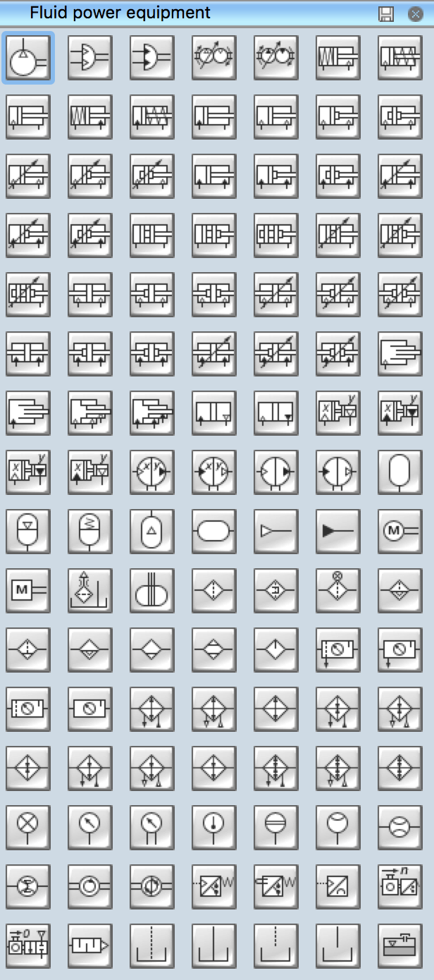
- Fluid Power - Equipment
he vector stencils library "Fluid Power Equipment" contains 113
symbols of hydraulic and pneumatic equipment including pumps, motors,
air compressors, cylinders, meters, gauges, and actuators. Use it to
design fluid power and hydraulic control systems.
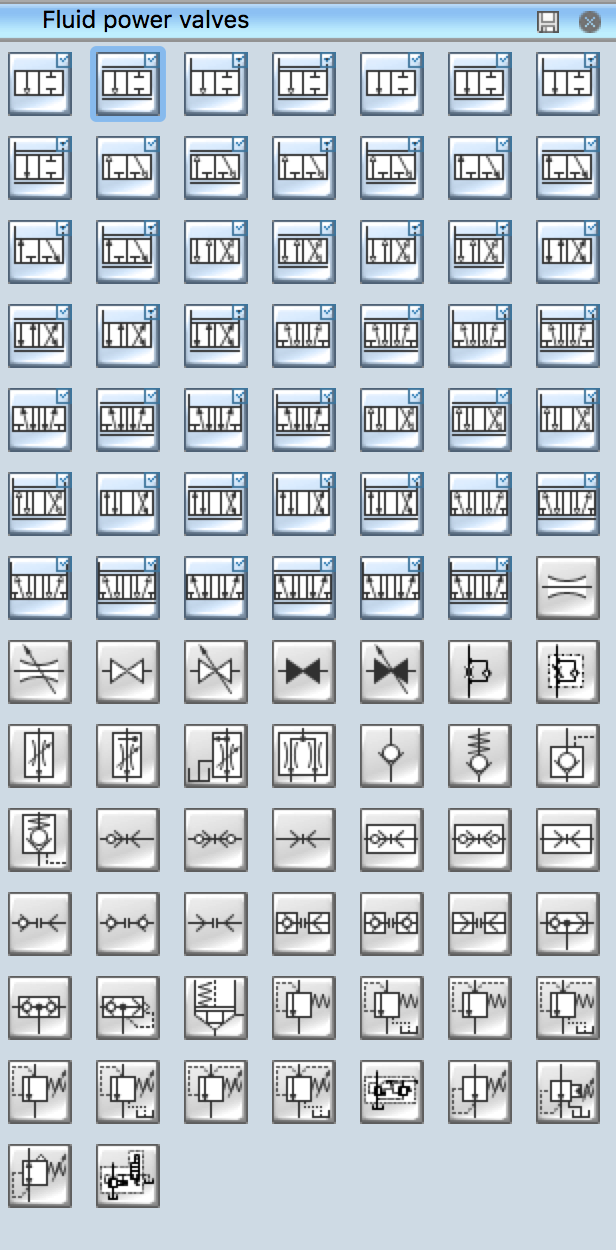
- Fluid Power - Valves
The vector stencils library "Fluid Power Valves" contains 93 symbols
of pre-made hydraulic and pneumatic valves, including directional
control valves, flow control valves, pressure control valves, and
electrohydraulic and electropneumatic valves.
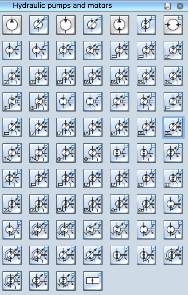
- Hydraulic Pumps and Motors
The vector stencils library "Hydraulic Pumps and Motors" contains 74
symbols of hydraulic pump vector stencils, hydraulic motor symbols for
engineering drawings of fluid power and hydraulic control systems.
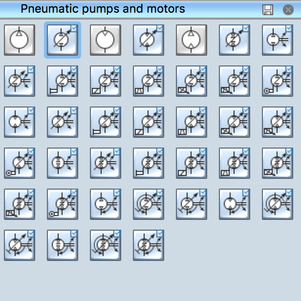
- Pneumatic Pumps and Motors
The vector stencils library "Pneumatic Pumps and Motors" contains 39
symbols of pneumatic pumps, motors and pump-motors for designing the
engineering drawings of pneumatic circuits.
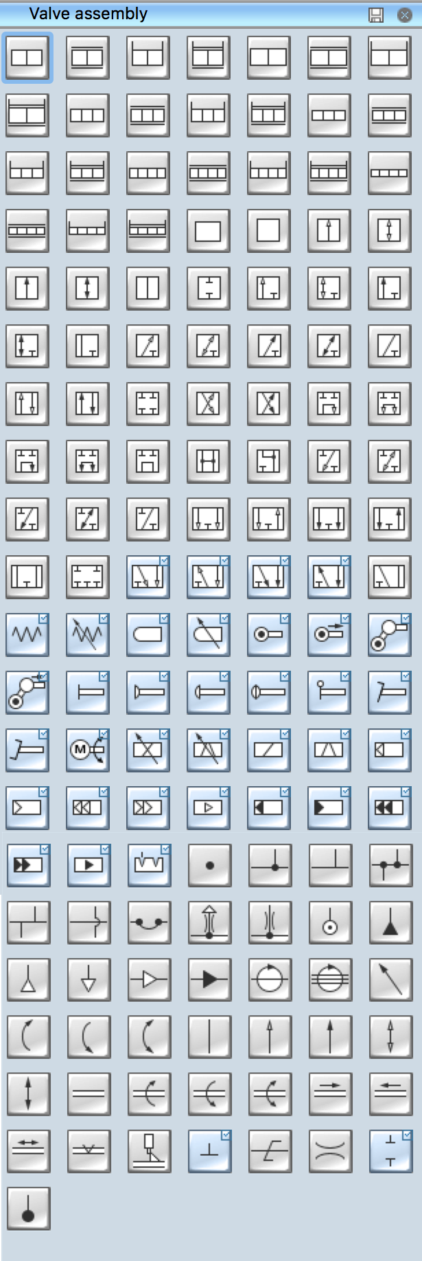
- Valve Assembly
The vector stencils library "Valve Assembly" contains 141 symbols of
pressure and flow regulators, flow direction indicators, controls, and
symbols to design flow paths of control valves. Use these valve assembly
shapes to design the engineering drawings of hydraulic and pneumatic
valve assemblies in fluid power systems.
- Welding
The vector stencils library "Welding" contains 38 welding joint
symbols to identify fillets, contours, resistance seams, grooves,
surfacing, and backing. Use it to indicate welding operations on working
drawings.

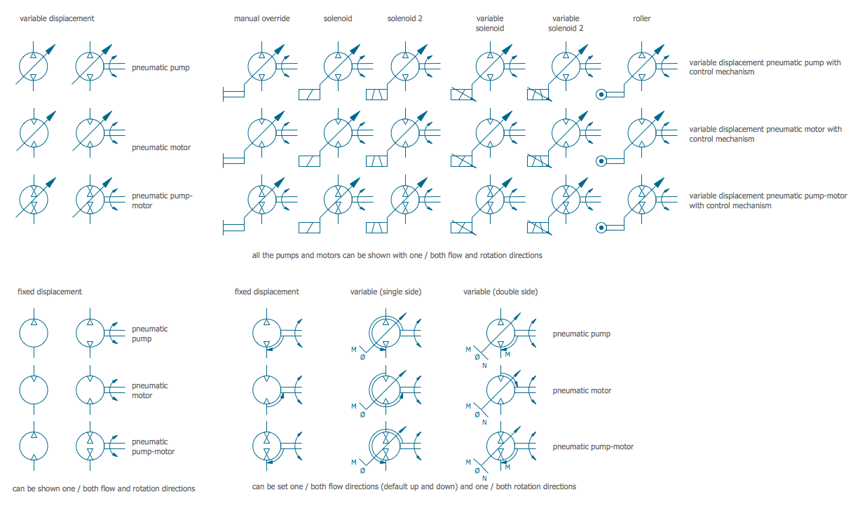
Example 2. Mechanical Drawing Symbols - Pneumatic Pumps and Motors Library
To design your own Mechanical Drawing in minutes, follow the next steps:
- create new ConceptDraw document,
- drag the required objects from the libraries,
- arrange and connect these objects,
- type the text and apply colors, if needed.


Follow Us
Stay updated via social channels