
(Projections, Views, Drawing Instruments, Lines,
Geometric figures, Symbolic Representation) (5 – 6 Q)
Definition :
An engineering drawing, a type of technical drawing, is used to fully and clearly define requirements for engineered items. Engineering drawing (the activity) produces engineering drawings .
These are the most basic and the foundation of Engineering drawing.
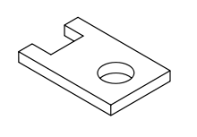
- Isometric Drawing.
- Orthographic or Multiview Drawings.
- Dimensioning.
- Sectioning.
- Drawing Tools.
- Assembly Drawings.
- Cross-Sectional Views.
- Half-Sections.
A multiview projection is a type of orthographic projection that shows the object as it looks from the front, right, left, top, bottom, or back (e.g. the primary views), and is typically positioned relative to each other according to the rules of either first-angle or third-angle projection. The origin and vector direction of the projectors (also called projection lines) differs, as explained below.
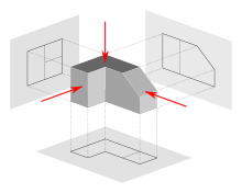
1.In first-angle projection, the parallel projectors originate as if radiated from behind the viewer and pass through the 3D object to project a 2D image onto the orthogonal plane behind it. The 3D object is projected into 2D "paper" space as if you were looking at a radiograph of the object: the top view is under the front view, the right view is at the left of the front view.
2.In third-angle projection, the parallel projectors originate as if radiated from the far side of the object and pass through the 3D object to project a 2D image onto the orthogonal plane in front of
it. The views of the 3D object are like the panels of a box that
envelopes the object, and the panels pivot as they open up flat into the
plane of the drawing. Thus the left view is placed on the left and the top view on the top;
and the features closest to the front of the 3D object will appear
closest to the front view in the drawing.

Auxiliary views :
- An auxiliary view is an orthographic view that is projected into any plane other than one of the six primary views.
- These views are typically used when an object contains some sort of inclined plane.
- Using the auxiliary view allows for that inclined plane (and any other significant features) to be projected in their true size and shape.
- The true size and shape of any feature in an engineering drawing can only be known when the Line of Sight (LOS) is perpendicular to the plane being referenced.
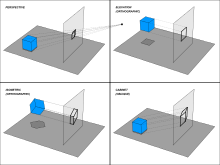
Isometric projection :
An isometric projection shows the object from angles in which the scales along each axis of the object are equal. Isometric projection corresponds to rotation of the object by ± 45° about the vertical axis.


Follow Us
Stay updated via social channels